PDF Instructions in (Spanish) [849K] submitted of Jon, EA2SN
Building Instructions:
1. Inventory all Parts
2. Install all Resistors.
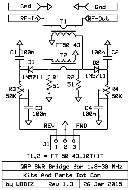
____R1,2: 51 (1/2 Watt) Green-Brown-Black-Gold
Note: R3,4 controls the output of the SWR bridge.
____R3,4: 50K ohm pot
3. Install all capacitors.
____C1,2,3,4: SMT or 100n brown labeled 104
We highly recommend installing the SMT caps vs the thru hole types
The SMT caps provide better RF shunting to ground
4. Install the detector Diodes.
____D1,2: 1N5711 - install flush against PCB per parts markings
Do not overheat when soldering.
5. Wind and install the RF coupling transformers.
____T1 & T2: Wind 10/12 turns of 25 ga wire on both FT50-43 ferrite toroids.
For 3.5 - 30 MHz, use 10 turns (more sensitive at low power)
For 1.8 - 30 MHz, use 12 turns (less sensitive at low power)
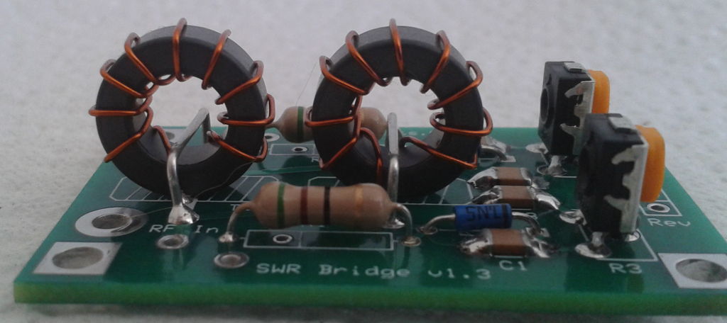
Wind the wire (12") on the toroid clockwise.
Trim the wires of T1 & T2 to a half inch.
Strip the insulation off the wires using sidecutters, scissors or sandpaper.
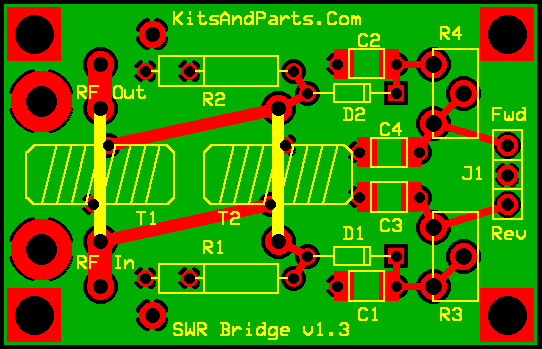
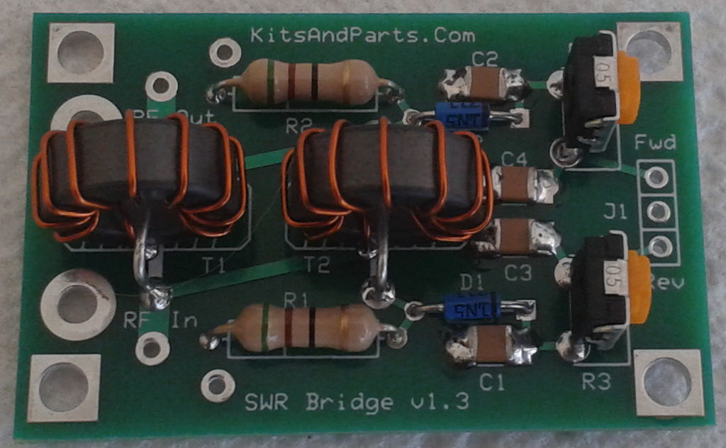
Install the wound toroids on the PCB and trim leads from the PCB.
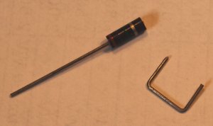
Cut both leads from the 1 Watt power resistor
Bend the cut leads to 7/16 inch cross section "U" shape.
Install the leads thru T1 & T2 and solder per the picture and schematic.
6. Connections.
Connect the bridge to a 5W RF source(in) and a 50 ohm dummy load(out).
Connect two mechanical meters to J1 or one meter with a SPDT switch.
Note: Meters are NOT supplied in the kit.
Adjust both R3 & R4 to mid-range.
Apply 5 Watts and adjust R4 for a full scale reading.
Reverse the RF connections so that the dummy load is at the input.
Apply 5 Watts and adjust R3 for a full scale reading.
The SWR Meter is now ready to use (5 watts full scale).
Designed for a maximum of 100 Watts (intermittent).