Add a 16x2 backlit LCD Display or buy your own display from Mouser
This Frequency Counter Development Kit is fully functional with the included pre-programmed microprocessor.
You have the option to modify the micros functions with the tools used in the documentation.
The internal firmware may optionally display your call sign upon request.
line1: " 16 char text " - (custom programmed upon request including amateur radio call)
line2: "nn,nnn.nnn Khz " - (where nn,nnn.nnn is the Frequency)
This Frequency Counter project is fully documented in the qrparci.org QRP Quarterly magazine in four consecutive issues starting with the Fall 2009 issue.
Magazine Article Part-1 Magazine Article Part-2 Magazine Article Part-3 Magazine Article Part-4
And here are the Addendum web-pages: Addendum Pages
This Freq Ctr was originally designed to be used as a Frequency Display receivers/transmitters.
Due to many request for 1 Hz frequency resolution, we have upgraded the Firmware.
See OPTIONS Below. The documented project starts with the installation of Linux (Mint Version) on a PC and installing the required tools on the Linux PC to draw the schematic, design the Printed Circuit Boards and write the assembler code for the freq counter, including all steps required for the reader to duplicate the Freq Counter project from concept to production. You may also follow the project on a Microsoft Windows platform; most instructions in the articles will apply to Windows, but here we are emphasizing the Linux platform for development because...it's free).
1. Solder the three (3) pre-inserted IC sockets.
2. Install all Resistors.
Note: Bend the resistor leads a sharp 90 degrees from the body
____R1: 10 Brown-Black-Black-Gold
____R2:430 Yellow-Orange-Brown-Gold
____R3:430 Yellow-Orange-Brown-Gold
____R4:680 Blue-Gray-Brown-Gold
____R5: not installed
____R6:1K Blue trimmer pot
Resistor R7 (to pin15 on LCD) value depends upon the type of LCD LED backlight.
If a resistor is included with the LCD, use that resistor for R7
R7 is not installed if your LCD has no LED backlight.
LCDs are available from Mouser.com or Kitsandparts.com
For a GREEN backlight fromn kitsandparts.com, R7 is a 100 ohm resistor.
____R7:100 Brown-Black-Brown-Gold
The next resistor, R8, a 4K7 is marked as R7 on the PCB, near R6, the blue 1K pot.
____R8:4K7 Yellow-Violet-Red-Gold
3. Install J3 & J4, 6 pin headers.
____See OPTIONS below to learn to reconfigure the Freq Ctr.
____Install the RED jumper on J4 to connect the right 2 pins, next to C9
4. Install all capacitors.
optionally, straighten the capacitor leads to solder flush to the PCB
____C1 100n
____C2 47u
____C3 100n
____C4 150p
____C5 100n
____C6 47u
____C7 100n
____C8 22p
____C9 40p Yellow Trimmer. Install in proper orientation with flat side toward X1
____C10 not installed
____C11 100n
____C12 100n
5. Crystal X1.
____Install the 20.48 Crystal. Leave a very small space (1/16 inch) under the crystal to prevent shorts.
6. Install all Diodes.
____D1 1N4148. Install in proper orientation with flat band toward the outer edge of the PCB.
____D2 1N4148. Install in proper orientation with flat band toward U3.
____D3 Install Yellow LED Diode, text on diode next to U1 socket.
7. Install the Reset Switch.
____S1 Orient the push button switch for easy insertion into the PCB.
8. Install the 7805 Voltage Regulator.
____U2 Orient 7805 with the TAB side towards the Yellow LED
9. Install programming Header.
____ - used to connect to an AVRISP Programmer to modify the Freq Counter Firmware
Now is a good time to test the Voltage Regulator on the board. Apply power (9-14 VDC) via J1 and measure 5 VDC between pins 10 and 20 of socket U4. If you do not measure 5 VDC +/- 0.1 Volts, fix the problem before proceeding.
10. LCD Connection.
Install the 16 pin male or female header socket on the top of the PCB
The oposite header will connect to the LCD, mounted on the bottom of the LCD
Make sure PIN-1s on the PCB and the LCD are in alignment
Pins 15 and 16 on the LCD connection are for LCDs that have an LED backlight.
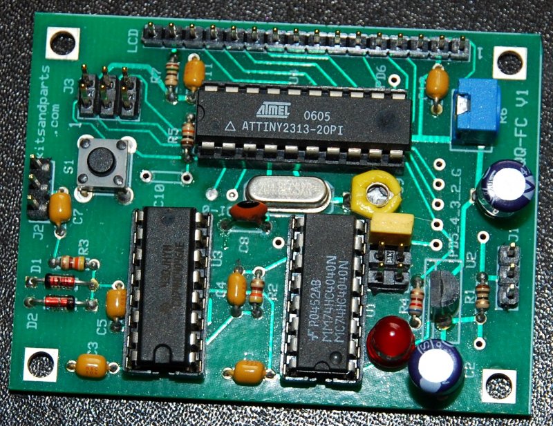
11. Install the 16-pin ICs. Use precautions when handlimng the ICs to prevent Static Electricity damage.
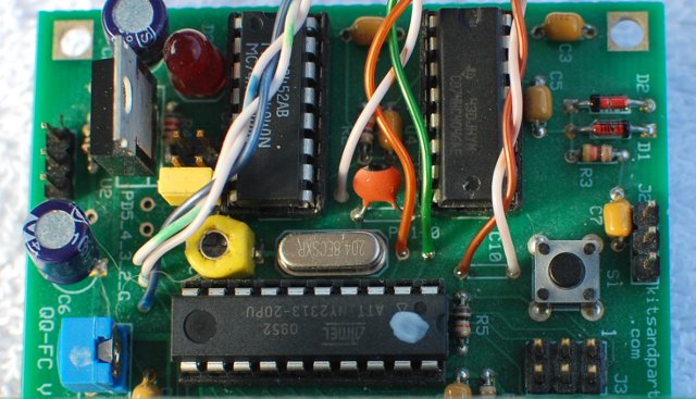
____U1 MC74HC4040N - Insert the IC per the above picture. CAUTION: Note the ICs orientation.
____U3 CD74HC4046AE - Insert the IC per the above picture. CAUTION: Note the ICs orientation.
12. Install the 20-pin ATtiny2313-20PU or ATtiny2313A-20PU IC.
____U4 Insert the IC per the above picture. CAUTION: Note the ICs orientation.
At this point, the Frequency Counter is complete.
Power (9-14 VDC) is applied to J1, Pin-2 is + and Pins 1:3 are ground.
RF input is at J2, with Pin-2 being the signal input and Pins 1:3 are ground.
Input amplitude should be a minimum of 50 to 100 mVolts P-P for proper operation.
Overvoltage protection is provided by D1 and D2; max input is 12 volts P-P.
The pre-programmed GATE TIME is 1/2 second and the DISPLAY RESOLUTION is 8 Hz
OPTIONS: Changing modes of operation, including GATE time and PRESCALER
The PRESCALER is set using a jumper on J4 next to U1
The default PRESCALE is divide by 4 (jumper nearest C9, connects U1:Q2 to U4:PD5)
The default connection allows freq. measurement up to about 36 MHz
The middle jumper is divide by 2 (connects U1:Q1 to U4:PD5)
The middle connection allows freq. measurement up to about 18 MHz
The last jumper is divide by 1 (connects clock input U1:CP to U4:PD5)
This connection allows freq. measurement up to about 9 MHz
When the PRESCALE jumper is moved, the Firmware needs to know about it
so that it can display the frequency correctly.
This is accomplished by connecting an ON-OFF-ON switch to U4 pins PD0 and PD1 and GND
The lower the PRESCALE, the better the frequency resolution for a set GATE time
Another ON-OFF-ON switch is connected to U4 pins PD2 and PD3 and GND to control GATE time.
The following table shows all nine possible modes of operation:
| Mode | Preselector | Gate Time | |||
|---|---|---|---|---|---|
| J4 Jumper | PD0 | PD1 | PD2 | PD3 | |
| 9 MHz Max 1 Hz Res 1 Sec Gate | U1:CP connect to U4:PD5 | Ground | Open | Ground | Open |
| 9 MHz Max 2 Hz Res 1/2 Sec Gate | U1:CP connect to U4:PD5 | Ground | Open | Open | Open |
| 9 MHz Max 4 Hz Res 1/4 Sec Gate | U1:CP connect to U4:PD5 | Ground | Open | Open | Ground |
| 18 MHz Max 2 Hz Res 1 Sec Gate | U1:Q1 connect to U4:PD5 | Open | Ground | Ground | Open |
| 18 MHz Max 4 Hz Res 1/2 Sec Gate | U1:Q1 connect to U4:PD5 | Open | Ground | Open | Open |
| 18 MHz Max 8 Hz Res 1/4 Sec Gate | U1:Q1 connect to U4:PD5 | Open | Ground | Open | Ground |
| 36 MHz Max 4 Hz Res 1 Sec Gate | U1:Q2 connect to U4:PD5 | Open | Open | Ground | Open |
| 36 MHz Max 8 Hz Res 1/2 Sec Gate | U1:Q2 connect to U4:PD5 | Open | Open | Open | Open |
| 36 MHz Max 16 Hz Res 1/4 Sec Gate | U1:Q2 connect to U4:PD5 | Open | Open | Open | Ground |
To select one of the above nine modes, either hard-wire your mode or connect
two (2) SPDT ON-OFF-ON switches such as mouser.com part# 506-A105SYCB04
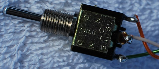
The GATE switch connects to PD3, PD2 and GND, the switch common connection
The PRESCALE switch connects to PD1 and PD2
The ground connection is available between U1 and the C8
Also recommend a Reset button/momentary switch connected to the holes for C10