The webpage is for historical reference only
Building Instructions:
1. Inventory all Parts
Note that there are two (2) binocular ferrites of the same size.
One is a type 43 material and the other is a type -61 material.
The binocular that has the 120 ohm resistor thru it is the -61
2. Install all 1/8 Watt and 1/4 Watt Resistors.
Note: Bend the resistor leads a sharp 90 degrees from the body
____R1: 470 Yellow-Violet-Brown-Gold
____R2: 1K Brown-Black-Red-Gold
____R3: 51 Green-Brown-Black-Gold
____R4: 120 Brown-Red-Brown-Gold 1/4 Watt
Note: Do not install R4 if you plan to control the transmitter with power from J2
____R5: 180 Brown-Gray-Brown-Gold
Note: R6 controls the output of the QRP Amp by controlling the gain of the driver Q1.
____R6: 10K ohm pot
3. Install all capacitors.
____C1,3: 47n yellow labeled 473
____C2,5: 330n yellow box
____C4,6: 68n white box
Note: C7: 47p will be installed later
4. Install all Transistors.
____Q1: 2N5109 - install 1/10 inch or 2,5 mm spacing above the PCB
____Q2,3: 2SC5739 - use the 4-40 screw and aluminum nut for mounting
bend the leads 90 degrees per the below picture.
Apply heat-sink compound between Q2/Q3 and the PCB
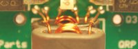
5. Wind and Install all Chokes and Transformers.
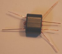
____T1: Wind 8 turns of dual 30 ga wire (Red&Green) on an FT37-43 ferrite toroid.
Wind the wire on the toroid clockwise.
Trim the wires of T1 to a half inch.
Strip the insulation off the wires using a hot solder iron.
One Red wire connects to one Green wire on the PCB
(top left hole and lower right hole of T1)
Install and trim leads from the PCB.
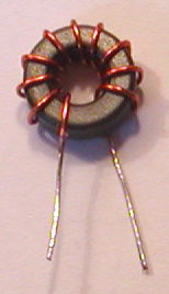
____L1: Wind 10 turns of 26 GA wire on an FT37-43 ferrite toroid.
Cut 8 inches of 26 GA wire. Wind the wire on the toroid clockwise.
Trim the wires of L1 to a half inch.
Strip the insulation off the wires using sidecutters or sandpaper and tin.
Install and trim leads from the PCB.
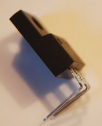
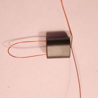
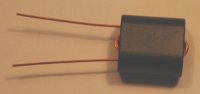
____T2: Wind 2 full turns of 26 GA wire through a shiny black BN-43-202 center tapped at 1 turn
Cut 6 inches of 26 GA wire. Fold the wire in half and insert into both holes of T2,
leaving a one inch loop. Wind each wire another 1/2 turn through the binocular.
You should now have 2 turns visible on the left side of T2
Fold back the two end wires and cut the loop of T2.
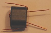
Strip the insulation off the right two wires using sidecutters or sandpaper.
Strip the insulation off the two left wires and tin. Cut to about 1/2 inch
Cut 6 inches of 26 GA wire. Fold the wire in half and insert into both holes of T2,
from the left side.
Wind each wire another 1/2 turn through the binocular.
Trim to one inch, Strip the insulation off the two wires using sidecutters or sandpaper.
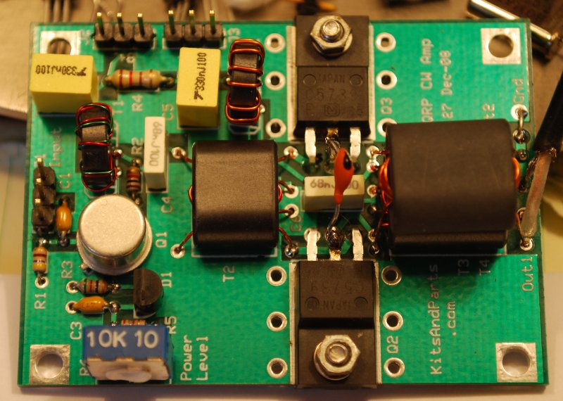
Align and Install T2 on the PCB into the holes per the picture.
Solder and trim leads.
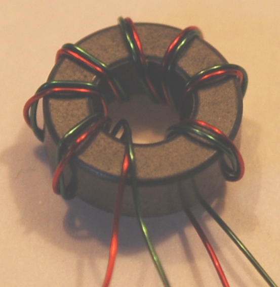
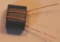
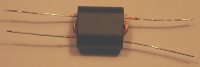
____T3: Wind 6 full turns of 26 GA wire through a BN-43-202 binocular, center tapped at 3 turns
Cut 15 inches of 26 GA wire. Fold the wire in half and insert into both holes of T3,
leaving a one inch loop.
Wind each wire 2 and 1/2 turns times more through the binocular.
You should now have 6 turns visible on the right side of T3.
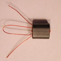
Strip the insulation off the two wire ends using sidecutters or sandpaper.
Fold back the two end wires and cut the loop of T3.
Strip the insulation off the new wire ends using sidecutters or sandpaper.
Align and Install T3 on the PCB into the holes per the picture.
Use the INSIDE 4 holes for mounting. Solder and trim leads.
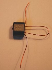
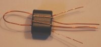
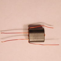
____T4: Wind 2 sets of 6 full turns of 26 GA wire through a BN-61-202 binocular.
Cut 13 inches of 26 GA wire. Fold the wire in half and insert into both holes of T4,
Wind each wire 2 and 1/2 turns times more through the binocular.
Trim both wires to one inch.
Cut another 13 inches of 26 GA wire. Fold the wire in half and insert into both holes of T4, from the right.
Wind each wire 2 and 1/2 turns times more through the binocular.
Trim both wires to one inch.
Strip the insulation off the two wire ends using sidecutters or sandpaper.
Align and Install T4 on top of T3 per the picture. Use the OUTSIDE 2 smaller holes on the bottom of the PCB.
Solder and trim leads.
For unbalanced output, install a jumper from "GND" to the hole just to the left on the bottom edge of the PCB
For balanced output, do NOT install the jumper.
6. Install the PIN Diode.
____D1: MPN3700 - install flush against PCB per parts markings
DO NOT OVERHEAT WHEN SOLDERING
7. Install C7.
C7 is soldered to both collectors of Q2 and Q3 over C6 on the top side of the PCB
____C7: 47p (see picture)
8. Connections.
Connect a 40 or 20 meter LowPassFilter to the output of the Amp.
Connect a 5 Watt dummy load to the output of the LowPassFilter.
Connect your RF source (~1 mW) to J1; either 7 or 14 MHz
Connect +12V to J3, include +8V from J2 if R4 was not installed.
Adjust R6 for desired RF output to the dummy load.
The 5 Watt QRP Amp is now finished. Go QRV and hold a CW QSO.