
1. Inventory all Parts - note the small Surface Mound Ring Diode in the bag
Note that the 6 capacitor values may be 47n or 100n and
they may be axial or radial leads.
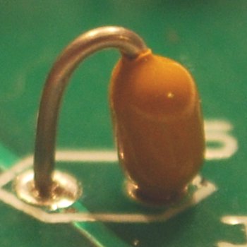
2. Install the SMD quad ring diode - HSMS-2829.
Create a tool to hold the SMD in place on the PCB.
I used a tooth pick with the tip cut off.
Be careful installing the diode ring. It is very easy for the part to pop out of a holding tool and you end up loosing the part on the floor never to be seen again.
Align the SM device with the PCB mask (note the larger pad on PIN-1) and tack solder one of the pads. Then solder the remaining pads.
If you have a multimeter with a Diode Measure option, you should measure a voltage drop of about 0.56 volts in both directions of pins 1 and 2, and repeat for pins 3 and 4 of the Ring Mixer.
3. Install both Resistors.
Note: Bend the resistor leads a sharp 90 degrees from the body
____R1,2: 1K Brown-Black-Red-Gold
4. Install all six capacitors.
Note: Bend the capacitor leads a sharp 90 degrees from the body
If the caps have radial leads, straighten the leads to fit the 0.1 inch holes.
If the caps have axial leads, bend one lead 180 degrees at the body of the cap.
____C1,2,3,4,5,6: 47n or 100n
5. Install Transformers.
T1____Cut the two-colored twisted pair wire into three 6-inch pieces.
Using one 6 inch wire pair, Wind 3 turns tight thru T1 without scraping the insulation of the wire. Make sure the wire is twisted about 2 to 3 twists per inch. Cut any excess lead length so that only one (1) inch remains. Strip some of insulation from the wire pigtails up to about 1/16 of an inch from the body of T1. This wire is somewhat heat strip-able but requires some extra heat and time. After the wires are stripped and tinned, twist together one red and one green wire to form a center tap for T1.
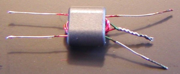
Using another 6 inch wire pair, unwind and serparate the wires. Insert one wire 3 full turns thru T1 holes, trim, strip and tin. T1 transformer should like the picture above.
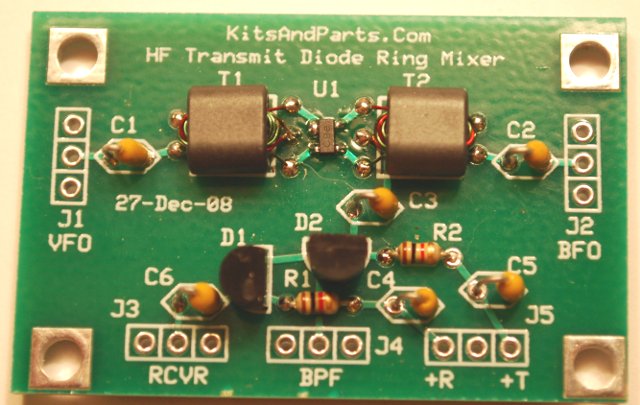
Install T1 into the circuit board per picture below.
T2____Repeat instruction for T1.
6. Install the PIN Diodes.
____D1,2: MPN3700 - install flush against PCB per parts markings
DO NOT OVERHEAT WHEN SOLDERING.
Theory of Operation:
This Mixer is only active in transmit mode.
Transmit mode is defined as applying +8V at "+T" on J5. In Transmit mode,
PIN Diode D2 turns ON and passes the output of the quad ring mixer to the
Band-Pass-Filter. Source signals, both VFO and BFO should be +5dBm
or 1.4 volts P-P from 50 ohm sources.
In Receive mode, +8V is applied to "+R" on J5 which turns on D1 and
passes RF from the Band-Pass-Filter to the receiver front end.