Available Now
Functions & Specs:
All Ports are 50Ω
+7dBm Local Oscillator Injection Design
Full Diplexer at the IF Port
Optional Attenuators for RF & LO Ports
This kit does NOT include:
_____ External Connection Cables
_____ Enclosure
For Solder Pencil Soldering, this kit recommends:
_____ Good Quality 45 Degree Diagonal Tweezers.
_____ HAKKO FX-888D Temperature Controlled Solder Pencil.
_____ CircuitWorks CW 3220 Liquid Flux.
_____ Kester Solder 63/37 .028 - use for other parts.
For Hot Air Soldering, this kit recommends:
_____ Hot Air Gun Model 858D (or better).
Search http://ebay.com for item # 274463047101
_____ CircuitWorks CW 3220 Liquid Flux.
Search http://ebay.com for item # 202373307435
_____ Kester Solder 63/37 .020 (0,5 mm) - use for SMDs.
_____ Mechanic Solder Paste XGZ40 63/37 Paste/Flux 183 Deg C, IPX3, 35g
Search http://ebay.com for item # 223803694552
Production Generic DBDM Mixer Schematic: ExpressPCB Schematic Source File
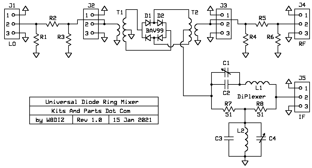
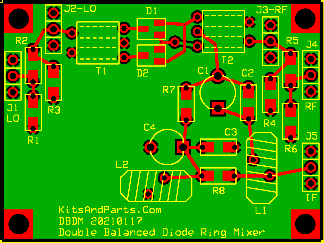
Production Generic DBDM Mixer PCB: ExpressPCB Board Layout Source File
PCB is 1.5 x 2.0 inches
Building Instructions:
1. DO NOT remove any parts from the kit until instructed to do so.
How to wind Toroids for this kit.
2. Some helpful SMT Info / Links
Surface-Mount Soldering Notes by W8BH, Bruce Hall

Youtube Link About Desoldering And Flux

Youtube Link About Capacitors

Youtube Link General SMT Tutorial

Youtube Link Hot Air SMT
3. Try to limit the handling of the SMT parts; they have a tendancy to disappear.
If using a hot air gun, you may 0wish to organize the parts installation into sections.
4. Install the unmarked capacitor
_____ C3 - 1000pF - qty 1 - install and solder.
5. Install the two SMD 1206 resistors.
_____ R7,8 - 51Ω - qty 2 - labeled as 510
_____ R1,2,3 - install any optional LO Port Attenuator Resistors
_____ R4,5,6 - install any optional RF Port Attenuator Resistors
_____ install jumper wires across R2 and R5 if NOT installing Attenuators
6. Install the two Dual BAV99 Diodes labeled KJE50
_____ D1,2 - BAV99 Diodes labeled KJE50 - install and solder.
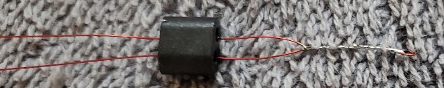
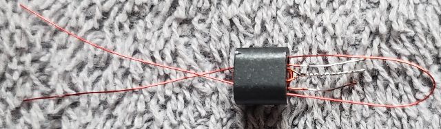
7. Build & Install Balun Transformers T1 & T2 - Identical Transformers for most HF Mixers
Make two (2) sets - for T1 & T2
_____ Cut 9" of #34 red magnet wire.
_____ Wind 6 turns of #34 red wire on ferrite binocular center-tapped at 3 turns
Fold the 9" wire in half
Twist the folded end for half an inch and tin with solder
Insert each wire through the ferrite balun as shown
Fold each wire through the opposite balun hole
Repeat until you have a total of 6 full turns
That is 3 full turns for each wire starting at the center tap
Trim the wire ends to half an inch, then tin with solder

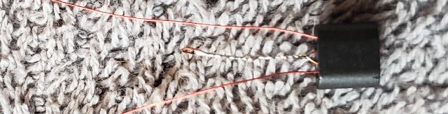
_____ Cut 4" of #34 red magnet wire.
_____ Wind 3 turns of #34 red wire on ferrite binocular
Fold the 4" wire in half
Insert each wire through the ferrite balun as shown
Run each wire through the balun hole 2 more times
This is 3 full turns
Trim the wire ends to half an inch, then tin with solder
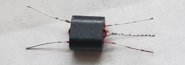
_____ Install T1 & T2 on the Mixer PCB
8. Install the 3-Pin headers onto the PCB
9. Install Trimmer Capacitor
_____ C1 (C4 not required) - install the Brown Trimmer - Note Orientation
10. Create & Install IF Diplexer Inductor L2
L2 is a T37-17 toroid colored blue & yellow
Select your IF from the table and cut the required red magnet wire.
Wind wire evenly over the entire toroid.
Trim the wire ends to half an inch, then tin with solder and install on the PCB
Optional: Verify that L2 & C3 are resonant at the IF using a Scope/SigGen or a Spectrum Analyzer.
| IF | L1 Turns-Inches | L2 Turns-Inches |
|---|---|---|
| 4 MHz | FT37-61 26T-16" | T37-17 31T-18" |
| 5 MHz | FT37-61 21T-13" *** | T37-17 24T-15" *** |
| 6 MHz | FT37-61 17T-11" | T37-17 21T-13" |
| 7 MHz | FT37-61 15T-10" | T37-17 18T-12" |
| 8 MHz | FT37-67 22T-13" | T37-17 15T-11" |
| 9 MHz | FT37-67 20T-12" *** | T37-17 13T-10" *** |
| 10 MHz | FT37-67 18T-12" | T37-0 22T-13" |
| 11 MHz | FT37-67 16T-11" | T37-0 20T-12" |
| 12 MHz | FT37-67 15T-10" | T37-0 18T-12" |
| 13 MHz | FT37-67 14T-10" | T37-0 16T-11" |
| 14 MHz | FT37-67 13T-9" | T37-0 15T-10" |
| 15 MHz | FT37-67 12T-9" | T37-0 13T-10" |
| 16 MHz | FT37-67 11T-8" *** | T37-0 11T-10" *** |
*** actual measured and tested values
11. Create & Install IF Diplexer Inductor L1
L1 is either a black FT37-67 or black FT37-61 (see table)
The FT37-67 is in the SMD parts bag
Select your IF from the table and cut the required red magnet wire.
Wind wire evenly over the entire toroid.
Trim the wire ends to half an inch, then tin with solder and install on the PCB
Optional: Verify that L1 & C1 are resonant at the IF using a Scope/SigGen or a Spectrum Analyzer.
Parts List:
R7,8 - 2 each 51 Ohm labeled 510
R1,3 - 2 each 300 Ohm labeled 301
R2 - 1 each 18.2 Ohm labeled 18R2
C3 - 1 each 1000pF NPO 50V not labeled
C1 - 1 each 60 pF Brown Trimmer
3 each 3-Pin Headers
D1,2 - 2 each BAV99 dual diodes labeled KJE50
L2 - 1 each T37-0 Rust Colored Phenolic Toroid
L2 - 1 each T37-17 Blue & Yellow Powdered Iron Toroid
L1 - 1 each FT37-67 Black Ferrite Toroid (in SMD bag)
L1 - 1 each FT37-61 Black Ferrite Toroid (in main bag)
T1,2 - 2 each BN-43-2402 binocular
35 inches of red #27 magnet wire
26 inches of red #34 magnet wire

https://www.pasternack.com/t-calculator-pi-attn.aspx
http://leleivre.com/rf_pipad.html
3 dB 300-18-300 (R1 - R2 - R3)
4 dB 220-24-220
6 dB 150-36-150