Build this Universal 10 watt Linear RF Amplifier - *SOLD OUT*
PDF Instructions in (English) [849K] submitted of Jon, EA2SN
PDF Instructions in (Spanish) [848K] submitted of Jon, EA2SN
PDF Instructions (Deutsch) [660K] submitted of Dieter, DL2BQD
PDF Instructions (Russian) [738K] submitted of Aleksey, RX3DVU
PDF Instructions (French) [1000K] submitted of Chris, F8CRM
Specs are:
12-15 Vdc operation with +8V XMIT/RCVE control
Source RF is the output from a standard +7 dBm
Diode Ring mixer via a 6 dB loss band pass filter.
Output is ~10 Watts SSB/CW
This kit to be available in April of 2008 and at Dayton FDIM 2008
Building Instructions:
1. Inventory all Parts
2. Install all 1/4 Watt Resistors.
Note: Bend the resistor leads a sharp 90 degrees from the body
____R4,5,6,7,8,13: 1R0 Brown-Black-Gold-Gold
____R18: 4R7 Yellow-Violet-Gold-Gold
3. Install all 1/8 Watt Resistors.
Note: Bend the resistor leads a sharp 90 degrees from the body
____R1,3,26,30,31: 1K0 Brown-Black-Red-Gold
____R2: 10K Brown-Black-Orange-Gold
____R9,10,14: 220 Red-Red-Brown-Gold
____R11,12: 33 Orange-Orange-Black-Gold
____R15,17: 470 Yellow-Violet-Brown-Gold
____R16: 2R2 Red-Red-Gold-Gold
____R19: 620 Blue-Red-Brown-Gold
____R20: 500 ohm pot
____R21,22,25,28: 100 Brown-Black-Brown-Gold
____R23: 750 Violet-Green-Brown-Gold
____R24: 10 Brown-Black-Black-Gold
____R27: 680 Blue-Gray-Brown-Gold
____R29: 1K2 Brown-Red-Red-Gold
4. Wind and Install all Chokes and Transformers.
Note that the two BN-61-202 binoculars are a dull gray while the BN-43-202 is shiny black
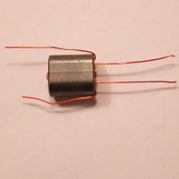
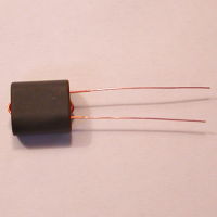
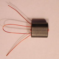
____L1: Wind 6 full turns of 26 GA wire through a shiny black BN-43-202 center tapped at 3 turns
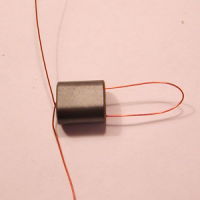
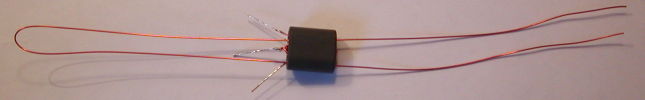
Cut 12 inches of 26 GA wire. Fold the wire in half and insert into both holes of L1,
leaving a one inch loop. Wind each wire 2 and 1/2 turns times more through the binocular.
You should now have 6 turns visible on the left side of L1
Fold back the two end wires and cut the loop of L1
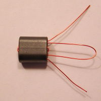
Strip the insulation off the two right wires using sidecutters or sandpaper.
Twist the wires together and solder together to create a centertap for L1
Strip the insulation off the two left wires and tin. Cut to about 1/2 inch
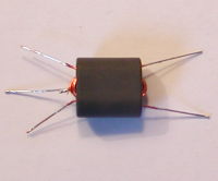
and form L1 per the picture.
Align and Install L1 on the PCB into the holes per the picture.
Solder and trim leads.
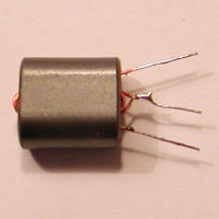
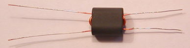
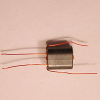
____T1: Wind 5 full turns of 26 GA wire through a BN-61-202 dull gray binocular
Cut 10 inches of 26 GA wire. Fold the wire in half and insert into both holes of T1.
Wind each wire 2 full turns more through the binocular.
You should now have 5 turns visible on the left side of T1
Temporarily, twist the two wires together so that winding the second layer will be easier.
Cut 15 inches of 26 GA wire. Fold the wire in half and insert into both holes of T1 from the right side.
Wind each wire 3 full turns more through the binocular.
Unwind and trim the wires on the 5 turn winding (right side) to 1.5 inches.
Strip the insulation off the two right wires using sidecutters or sandpaper and tin.
Trim the wires of T1 on the 7 turn winding (left side) to 2.0 inches.
Strip the insulation off the two left wires using sidecutters or sandpaper and tin.
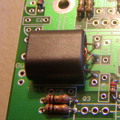
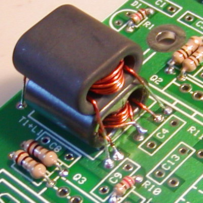
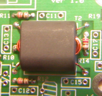
Align and Install T1 on top of L1 on the PCB.
Solder and trim leads.
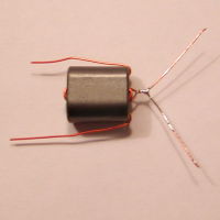
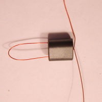
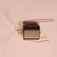
____T2: Wind 4 full turns of 26 GA wire through a dull gray BN-61-202 center tapped at 2 turns
Cut 10 inches of 26 GA wire. Fold the wire in half and insert into both holes of T2,
leaving a one inch loop. Wind each wire 1 and 1/2 turns times more through the binocular.
You should now have 4 turns visible on the right side of T2
Fold back the two end wires and cut the loop of T2
Strip the insulation off the two left wires using sidecutters or sandpaper.
Twist the wires together and solder together to create a centertap for T2
Strip the insulation off the two right wires and tin. Cut to about 1/2 inch
and form T2 per the picture.
Cut 15 inches of 26 GA wire. Fold the wire in half and insert into both holes of T2 from the left side.
Wind each wire 3 full turns more through the binocular. Trim to 2 inches.
Strip the insulation off the two right wires using sidecutters or sandpaper and tin.
Align and Install T2 on the PCB into the holes per the picture.
Solder and trim leads.
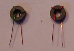
____L3 and L4: cut two inches off of the 10 inch piece of twisted 30 GA red/green wire.
Place three turns of either color wire on L3, a FT23-43 toroid
Repeat for L4. Strip the insulation using sidecutters or sandpaper and tin.
DO NOT INSTALL AT THIS TIME.
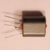
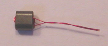
____T3: Wind 6 and 2 full turns of 30 GA wire through a BN-43-2402 small binocular
Locate the red 30 GA wire. Fold the wire in half and insert into both holes of T3.
Wind each wire another 2 and a 1/2 turn through the binocular.
You should now have 6 turns visible on the left side of T3
Temporarily, twist the two wires together so that winding the second layer will be easier.
Locate the green 30 GA wire. Fold the wire in half and insert into both holes of T3 from the left side.
Wind each wire 1/2 turn more through the binocular.
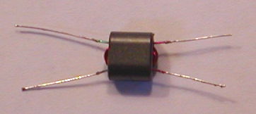
Unwind and trim the wires on the 6 turn winding (right side) to a half inch.
Strip the insulation off the two right wires using sidecutters or sandpaper and tin.
Trim the wires of T3 on the 2 turn winding (left side) to a half inch.
Strip the insulation off the two left wires using sidecutters or sandpaper and tin.
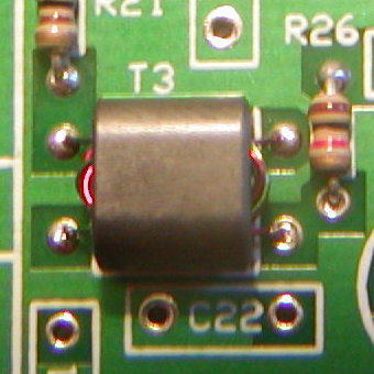
Align and Install T3 on the PCB.
Solder and trim leads.
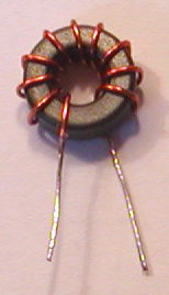
____L2,5,6,7: Wind 10 turns of 26 GA wire on an FT37-43 ferrite toroid.
Cut 8 inches of 26 GA wire. Wind the wire on the toroid clockwise.
Trim the wires of L2 to a half inch.
Strip the insulation off the wires using sidecutters or sandpaper and tin.
DO NOT INSTALL THE CHOKES AT THIS TIME.
5. Install all capacitors.
____C1,3,6,7,8,9,11,12,18,19,24,25,28,29,31: 10n
____C2,4,13,15,21,22,26,27: 100n
Straighten blue 100n capacitor's leads before installing.
____C17: 220p
____C5,14,16,20,23,30: 330n
Note that C30 fits tight against R29
____C10: 47uF or 33uF - observe polarity
6. Install all Diodes.
____D1,2,4,5: MPN3700 - install flush against PCB per parts markings
DO NOT OVERHEAT WHEN SOLDERING
____D3: 1N4001 - note the polarity band
7. Install remaining chokes
____L3,4: 3 turn FT23-43 choke - install per parts markings on the PCB
____L2,5,6,7: 10 turn FT37-43 choke - install per parts markings on the PCB
8. Install all Transistors WITH Heat Sinks.
____Q5: 2N5109 - install 1/10 inch or 2,5 mm spacing above the PCB
____Q1: 2N3906 - install per parts markings on the PCB
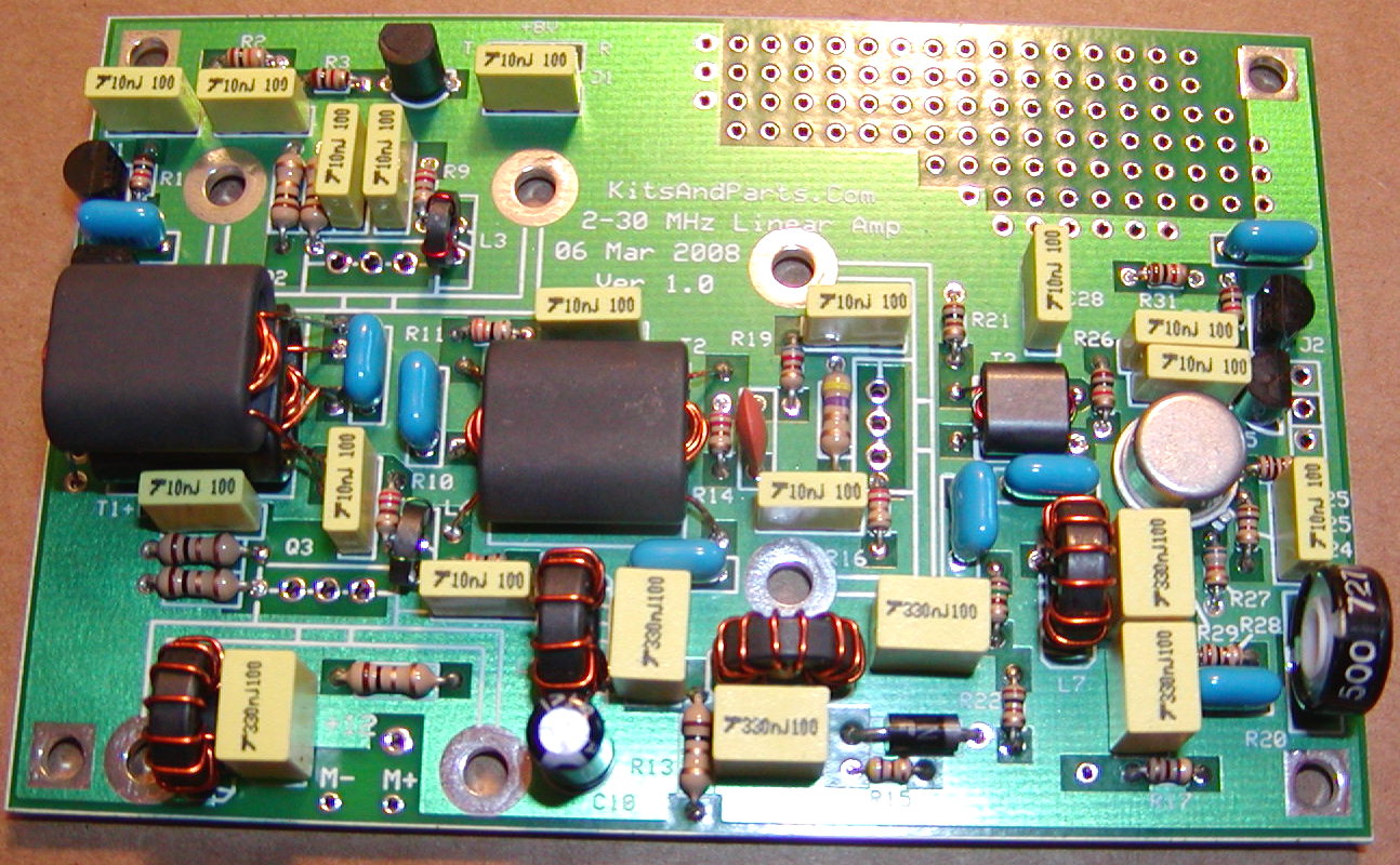
Here is a picture of the PCB without heat sinks
NOTE: The follow 3 transistors should use Heat Sink Grease
It is available from Radio Shack, part # 276-1372 @ $2.99
____Q2: 2SC5739 - Mount the transistor per parts markings on the PCB.
The transistor is mounted on the inside of the heat sink.
Use Heat Sink Grease between the Transistor and the heat sink.
Use a 4-40 scew and nut to secure the transistor to the heat sink.
Make sure the head of the screw faces away from the PCB (up)
____Q3: 2SC5739 - Mount the transistor per parts markings on the PCB.
The transistor is mounted on the outside of the heat sink.
Use Heat Sink Grease between the Transistor and the heat sink.
Use a 4-40 scew and nut to secure the transistor to the heat sink.
Make sure the head of the screw faces away from the PCB (down)
____Q4: 2SC5739 - Mount the transistor per parts markings on the PCB.
The transistor is mounted on the inside of the heat sink.
Use Heat Sink Grease between the Transistor and the heat sink.
Use a 4-40 scew and nut to secure the transistor to the heat sink.
Make sure the head of the screw faces away from the PCB (right)
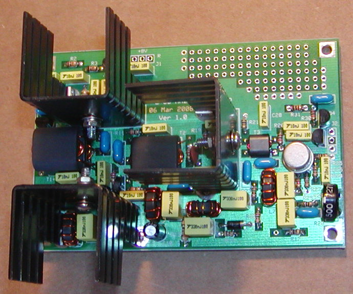
Here is a picture of the PCB with heat sinks
8. Miscellaneous Notes.
____R17: This resistor can optionally be 1/4 watt for higher heat dissipation.
Note the extra PCB mounting hole between R15 and R17.
For experimentor wanting to try different RF final amps.
____M1 % M+: These pads are available for measuring the BIAS currents of Q2 plus Q3.
50 milliamps per transistor or 100 milliamps total.
Adjust R20 (500 ohm pot) for desired bias current.
____J2 pin 2: The input of the Amp needs to be at DC ground for the PIN diodes D4,5 to function.
This can be achieved via a link coupling from the Band Pass Filter output,
or requires a 40uH choke to ground (10 turns on an FT37-43 ferrite toroid)
____J1: To test and/or operate the linear amp, you will need +8V at 500 mA and
XMIT and RCVE control signals at an 8 volt level.
When not active, the control signal levels should be at ZERO volts/ground.
PDF Instructions in (English) [849K] submitted of Jon, EA2SN
PDF Instructions in (Spanish) [848K] submitted of Jon, EA2SN
PDF Instructions (Deutsch) [660K] submitted of Dieter, DL2BQD
PDF Instructions (Russian) [738K] submitted of Aleksey, RX3DVU
PDF Instructions (French) [1000K] submitted of Chris, F8CRM
Specs are:
12-15 Vdc operation with +8V XMIT/RCVE control
Source RF is the output from a standard +7 dBm
Diode Ring mixer via a 6 dB loss band pass filter.
Output is ~10 Watts SSB/CW
This kit to be available in April of 2008 and at Dayton FDIM 2008
Building Instructions:
1. Inventory all Parts
2. Install all 1/4 Watt Resistors.
Note: Bend the resistor leads a sharp 90 degrees from the body
____R4,5,6,7,8,13: 1R0 Brown-Black-Gold-Gold
____R18: 4R7 Yellow-Violet-Gold-Gold
3. Install all 1/8 Watt Resistors.
Note: Bend the resistor leads a sharp 90 degrees from the body
____R1,3,26,30,31: 1K0 Brown-Black-Red-Gold
____R2: 10K Brown-Black-Orange-Gold
____R9,10,14: 220 Red-Red-Brown-Gold
____R11,12: 33 Orange-Orange-Black-Gold
____R15,17: 470 Yellow-Violet-Brown-Gold
____R16: 2R2 Red-Red-Gold-Gold
____R19: 620 Blue-Red-Brown-Gold
____R20: 500 ohm pot
____R21,22,25,28: 100 Brown-Black-Brown-Gold
____R23: 750 Violet-Green-Brown-Gold
____R24: 10 Brown-Black-Black-Gold
____R27: 680 Blue-Gray-Brown-Gold
____R29: 1K2 Brown-Red-Red-Gold
4. Wind and Install all Chokes and Transformers.
Note that the two BN-61-202 binoculars are a dull gray while the BN-43-202 is shiny black
____L1: Wind 6 full turns of 26 GA wire through a shiny black BN-43-202 center tapped at 3 turns
Cut 12 inches of 26 GA wire. Fold the wire in half and insert into both holes of L1,
leaving a one inch loop. Wind each wire 2 and 1/2 turns times more through the binocular.
You should now have 6 turns visible on the left side of L1
Fold back the two end wires and cut the loop of L1
Strip the insulation off the two right wires using sidecutters or sandpaper.
Twist the wires together and solder together to create a centertap for L1
Strip the insulation off the two left wires and tin. Cut to about 1/2 inch
and form L1 per the picture.
Align and Install L1 on the PCB into the holes per the picture.
Solder and trim leads.
____T1: Wind 5 full turns of 26 GA wire through a BN-61-202 dull gray binocular
Cut 10 inches of 26 GA wire. Fold the wire in half and insert into both holes of T1.
Wind each wire 2 full turns more through the binocular.
You should now have 5 turns visible on the left side of T1
Temporarily, twist the two wires together so that winding the second layer will be easier.
Cut 15 inches of 26 GA wire. Fold the wire in half and insert into both holes of T1 from the right side.
Wind each wire 3 full turns more through the binocular.
Unwind and trim the wires on the 5 turn winding (right side) to 1.5 inches.
Strip the insulation off the two right wires using sidecutters or sandpaper and tin.
Trim the wires of T1 on the 7 turn winding (left side) to 2.0 inches.
Strip the insulation off the two left wires using sidecutters or sandpaper and tin.
Align and Install T1 on top of L1 on the PCB.
Solder and trim leads.
____T2: Wind 4 full turns of 26 GA wire through a dull gray BN-61-202 center tapped at 2 turns
Cut 10 inches of 26 GA wire. Fold the wire in half and insert into both holes of T2,
leaving a one inch loop. Wind each wire 1 and 1/2 turns times more through the binocular.
You should now have 4 turns visible on the right side of T2
Fold back the two end wires and cut the loop of T2
Strip the insulation off the two left wires using sidecutters or sandpaper.
Twist the wires together and solder together to create a centertap for T2
Strip the insulation off the two right wires and tin. Cut to about 1/2 inch
and form T2 per the picture.
Cut 15 inches of 26 GA wire. Fold the wire in half and insert into both holes of T2 from the left side.
Wind each wire 3 full turns more through the binocular. Trim to 2 inches.
Strip the insulation off the two right wires using sidecutters or sandpaper and tin.
Align and Install T2 on the PCB into the holes per the picture.
Solder and trim leads.
____L3 and L4: cut two inches off of the 10 inch piece of twisted 30 GA red/green wire.
Place three turns of either color wire on L3, a FT23-43 toroid
Repeat for L4. Strip the insulation using sidecutters or sandpaper and tin.
DO NOT INSTALL AT THIS TIME.
____T3: Wind 6 and 2 full turns of 30 GA wire through a BN-43-2402 small binocular
Locate the red 30 GA wire. Fold the wire in half and insert into both holes of T3.
Wind each wire another 2 and a 1/2 turn through the binocular.
You should now have 6 turns visible on the left side of T3
Temporarily, twist the two wires together so that winding the second layer will be easier.
Locate the green 30 GA wire. Fold the wire in half and insert into both holes of T3 from the left side.
Wind each wire 1/2 turn more through the binocular.
Unwind and trim the wires on the 6 turn winding (right side) to a half inch.
Strip the insulation off the two right wires using sidecutters or sandpaper and tin.
Trim the wires of T3 on the 2 turn winding (left side) to a half inch.
Strip the insulation off the two left wires using sidecutters or sandpaper and tin.
Align and Install T3 on the PCB.
Solder and trim leads.
____L2,5,6,7: Wind 10 turns of 26 GA wire on an FT37-43 ferrite toroid.
Cut 8 inches of 26 GA wire. Wind the wire on the toroid clockwise.
Trim the wires of L2 to a half inch.
Strip the insulation off the wires using sidecutters or sandpaper and tin.
DO NOT INSTALL THE CHOKES AT THIS TIME.
5. Install all capacitors.
____C1,3,6,7,8,9,11,12,18,19,24,25,28,29,31: 10n
____C2,4,13,15,21,22,26,27: 100n
Straighten blue 100n capacitor's leads before installing.
____C17: 220p
____C5,14,16,20,23,30: 330n
Note that C30 fits tight against R29
____C10: 47uF or 33uF - observe polarity
6. Install all Diodes.
____D1,2,4,5: MPN3700 - install flush against PCB per parts markings
DO NOT OVERHEAT WHEN SOLDERING
____D3: 1N4001 - note the polarity band
7. Install remaining chokes
____L3,4: 3 turn FT23-43 choke - install per parts markings on the PCB
____L2,5,6,7: 10 turn FT37-43 choke - install per parts markings on the PCB
8. Install all Transistors WITH Heat Sinks.
____Q5: 2N5109 - install 1/10 inch or 2,5 mm spacing above the PCB
____Q1: 2N3906 - install per parts markings on the PCB
Here is a picture of the PCB without heat sinks
NOTE: The follow 3 transistors should use Heat Sink Grease
It is available from Radio Shack, part # 276-1372 @ $2.99
____Q2: 2SC5739 - Mount the transistor per parts markings on the PCB.
The transistor is mounted on the inside of the heat sink.
Use Heat Sink Grease between the Transistor and the heat sink.
Use a 4-40 scew and nut to secure the transistor to the heat sink.
Make sure the head of the screw faces away from the PCB (up)
____Q3: 2SC5739 - Mount the transistor per parts markings on the PCB.
The transistor is mounted on the outside of the heat sink.
Use Heat Sink Grease between the Transistor and the heat sink.
Use a 4-40 scew and nut to secure the transistor to the heat sink.
Make sure the head of the screw faces away from the PCB (down)
____Q4: 2SC5739 - Mount the transistor per parts markings on the PCB.
The transistor is mounted on the inside of the heat sink.
Use Heat Sink Grease between the Transistor and the heat sink.
Use a 4-40 scew and nut to secure the transistor to the heat sink.
Make sure the head of the screw faces away from the PCB (right)
Here is a picture of the PCB with heat sinks
8. Miscellaneous Notes.
____R17: This resistor can optionally be 1/4 watt for higher heat dissipation.
Note the extra PCB mounting hole between R15 and R17.
For experimentor wanting to try different RF final amps.
____M1 % M+: These pads are available for measuring the BIAS currents of Q2 plus Q3.
50 milliamps per transistor or 100 milliamps total.
Adjust R20 (500 ohm pot) for desired bias current.
____J2 pin 2: The input of the Amp needs to be at DC ground for the PIN diodes D4,5 to function.
This can be achieved via a link coupling from the Band Pass Filter output,
or requires a 40uH choke to ground (10 turns on an FT37-43 ferrite toroid)
____J1: To test and/or operate the linear amp, you will need +8V at 500 mA and
XMIT and RCVE control signals at an 8 volt level.
When not active, the control signal levels should be at ZERO volts/ground.