Available for 10, 12, 15, 17, 20, 30, 40, 80 and 160 meters.
When ordering, please specify the Band(s) you want in an EMAIL
or in the COMMENTS section of the PAYPAL order
Specs: These bandpass filters are tight, narrow bandwidth HF Filters.
The 3 dB bandwidth is about 90 KHz @ 7 MHz.
The 6 dB bandwidth is about 140 KHz @ 7 MHz.
Each BPF Kit is FOR ONE BAND ONLY.

Note#1: C3 & C6 for the 30 meter band may be 1.5 or 2.2 or 3.0 pF
Instructions:
1. Install C2, C4 and C7.
a. Install trimmer capacitors into their correct places per the above PCB layout.
Install with flat side of trimmer into square hole pad.
2. Install L2.
a. Cut the spool of Copper Colored Magnet wire into 3 pieces per the above table.
b. Wind L2 toroid in a clockwise direction - Toroid Winding Details Here
c. Prepare the toroid wires for soldering - Magnet Wire Soldering Details Here
This magnet wire uses three layers of Epoxy insulation and is NOT heat stripable.
d. Install and solder toroid inductor L2.
3. Install L1 and L3.
a. Review this example of a dual winding toroid for 30 meters.
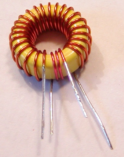 Click picture to enlarge
b. Wind L1 and L3 in a clockwise direction - Toroid Winding Details Here
c. Prepare the toroid wires for soldering - Magnet Wire Soldering Details Here
This magnet wire uses three layers of Epoxy insulation and is NOT heat stripable.
d. Install and solder toroid inductor L1 and L3.
4. Install C1, C5 and C8.
a. Install capacitors into their correct places per the above table.
5. Install C3 and C6.
a. Install capacitors into their correct places per the above table.
6. Connect the BPF via J1 and J2.